X-10 is a power line control protocol that makes relatively cheap home automation. I have a couple of $10 plug-in lamp modules that are controlled by a two channel wireless key chain transmitter. Well to be honest I also run Misterhouse on a Linux server with timers but we manually control these lights a lot and someone only needs a couple of lamp modules and the transmitter / receiver control to really change how they light up there house at night. So far I've not needed to correct any electrical issues in my home to successfully use X-10. The only "modification" I've made is to add the obligatory X-10 phase coupler and a whole house surge. The surge is so a lightning strike doesn't take out the whole X-10 system in a few microseconds. Well we got a Wii and now I have my first real issue that I can't overcome by simply using a different outlet.
Update 6/26/2009:
I noticed that BGMicro is selling a ferrite toroid (Amidon FT114-43) that is suitable and only needs 13 turns of wire. This can probably be turned with any wire available of suitable gauge. The only concern is that it might be too big to fit in your power strip.
Leviton 6287 Schematic
Leviton 6288 Schematic
FilterLinc 1626
Building your own Phase Coupler and Noise Blocker
These devices are rather complicated with multiple tuned LC circuits formed from inductors, high voltage capacitors, and fuses because high voltage capacitors fail short sometimes. I think these tuned circuits are needed to filter noisy equipment. If noise is the problem these are probably the thing to use and they are sufficiently complex that purchasing one is, I think, the best approach.
I decided to look at the problem from a different perspective. The only problem I have is with shunting. I know this because I know that the problematic devices have switching power supplies and I know that modern switching power supplies are required to have good noise filtering. The cheapest way to make a noise filter is with a capacitor which shunts high frequencies. Now, if you have "old" switching power supplies you might have a noise problem.
If I simply want to solve the shunting problem then the filter becomes much simpler and really does not need to be very precise. Ideally I would provide a filter that makes the connected load look like a high impedance at 120KHz, preventing that load from shunting the X-10 signal to ground. A simple LR circuit can easily make a good low pass filter with a really high input impedance above the low pass frequency. I decided to simply insert an inductor in the path between the power line and the load by modifying an off the shelf power strip. This allows me to simply plug all of my problematic devices into a power strip.
X10 Sucker Filter.xls - LR Low Pass Calculator
Popping this formula into a spreadsheet, I can vary the load Z and inductor Z over a range to determine the various cutoff frequencies. If the Z of the connected load is in the 10-500 ohm range then I need an inductor somewhere around 10mH. A 10mH inductor will have a cutoff frequency of 160Hz w/ 10 ohm load and 8KHz w/ 500 ohm load. Something near 10mH should work.

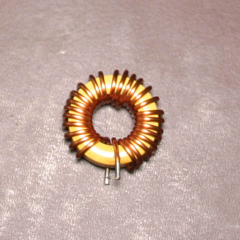
Core is yellow toroid with 25 turns of wire.
Wire diameter is .05"
Wikipedia AWG Chart
It must be 16 AWG; enough for 10A, probably OK for 15A given the short length. Ideally it would be 14AWG to match the 15A breaker in the power strip.
Powdered iron cores have standard colors that specify the core type and mine is yellow (6). Toroid cores also have standard sizes:
Iron Power Core Size Chart
Mine (plastic calipers) is .53" id, .95" od, .32" h ==> 13.5mm id, 24.1mm od, 7.87mm h
This matches a T-94 core size
Plugging this information into a calculator I found with Google:
66pacific.com Toroid Winding Calculator
says that I need ~400 turns to get 1mH (1000uH). 25 turns is ~5uH. Well I know it is not that low because I soldered it into a surge protector and it isolates the problematic devices. At 5uH the cutoff is ~3MHz so this can't be right.
Humm.. I wonder if it has a ferrite core?
Ferrite Core Size Chart
Looks like a T24 size core
Back to the winding calculator to pick Ferrite core. Well there are materials (e.g. 43) for a FT24 that give 1-10mH in the right turns ratio. That's probably what I have but there are just too many materials to be sure. I guess guessing is a bad idea.
Sorry, the end result is that I completely guessed at the suitability of the junk inductor based on the circuit where it came from. I think that unknown inductors must be electronically measured because I can not find a reliable way to determine the core material. If anyone knows how to do this drop me a comment. The end result is that you want to purchase or find a 5-10mH inductor with suitable power handling.


I would really like to have performed some real signal strength measurements, but I've never purchased a O-scope or X-10 strength meter. Maybe someone that lives in the DFW area can loan me one?
A few simple tests with a lamp module proved that the problem is solved. This goes to show that you don't need complicated test equipment to solve basic X-10 problems if you know a little theory. Ah, now to find another Saturday project.....
Table of contents
Update 6/26/2009:
I noticed that BGMicro is selling a ferrite toroid (Amidon FT114-43) that is suitable and only needs 13 turns of wire. This can probably be turned with any wire available of suitable gauge. The only concern is that it might be too big to fit in your power strip.
Introduction
X-10 suffers from both interference and from shunting of the signal. Interference occurs when a problem device in the home generates noise at the 120KHz frequency as either the primary frequency or a harmonic. Shunting of the signal occurs in problem devices that have power line filters designed to filter their own high frequency noise. These filters will many times shunt the X-10 signal to ground at the device effectively shorting out the signal. It turns out that in my home the latter is the only problem. I have a few devices that cause this problem most all seem to contain higher power switching power supplies. (e.g. Laptop power modules, Nintendo Wii, Nintendo Wii remote charger, and the battery charger for a scooter). We recently added a Nintendo Wii to our living room (the furthest point from the breaker panel) and now I can no longer control the lamps in that room. While shopping for a plug-in X10 filter, I thought about how hard it would be to modify the surge protector on the living room A/V equipment.Solution
There are several X-10 filters on the market that, based on user feedback, seem to perform well. However all of them are relatively expensive, easily exceeding the cost of an X-10 lamp module and they represent one "more" item that must be connected and managed. All of these filters are effective for both isolating a noisy device from the power line and for isolating a high frequency filter common in many switching power supplies. To accomplish both they generally have a decent notch filter that will not pass 120KHz and yet has a fairly high impedance at 120KHz from the power line side. These links provide some examples of typical filters:Leviton 6287 Schematic
Leviton 6288 Schematic
FilterLinc 1626
Building your own Phase Coupler and Noise Blocker
These devices are rather complicated with multiple tuned LC circuits formed from inductors, high voltage capacitors, and fuses because high voltage capacitors fail short sometimes. I think these tuned circuits are needed to filter noisy equipment. If noise is the problem these are probably the thing to use and they are sufficiently complex that purchasing one is, I think, the best approach.
I decided to look at the problem from a different perspective. The only problem I have is with shunting. I know this because I know that the problematic devices have switching power supplies and I know that modern switching power supplies are required to have good noise filtering. The cheapest way to make a noise filter is with a capacitor which shunts high frequencies. Now, if you have "old" switching power supplies you might have a noise problem.
If I simply want to solve the shunting problem then the filter becomes much simpler and really does not need to be very precise. Ideally I would provide a filter that makes the connected load look like a high impedance at 120KHz, preventing that load from shunting the X-10 signal to ground. A simple LR circuit can easily make a good low pass filter with a really high input impedance above the low pass frequency. I decided to simply insert an inductor in the path between the power line and the load by modifying an off the shelf power strip. This allows me to simply plug all of my problematic devices into a power strip.
Component Selection
What I need is an LR circuit forming a low pass with a cutoff somewhere significantly less than 120KHz. With the inductor facing the power line, this LR low pass will look like an open circuit (high impedance) to the 120KHz signal on the power line. This will effectively isolate the 120KHz signal sucking filter in the problematic device. The low pass cutoff needs to be high enough to stay away from the power line 60Hz frequency and low enough so that a simple one pole filter will significantly attenuate 120KHz. I'll say the range should be between 120Hz and 12KHz. The formula is Fc=Zload/(2*Pi*L). It is easy enough to solve for Fc, L, or R.X10 Sucker Filter.xls - LR Low Pass Calculator
Popping this formula into a spreadsheet, I can vary the load Z and inductor Z over a range to determine the various cutoff frequencies. If the Z of the connected load is in the 10-500 ohm range then I need an inductor somewhere around 10mH. A 10mH inductor will have a cutoff frequency of 160Hz w/ 10 ohm load and 8KHz w/ 500 ohm load. Something near 10mH should work.
Finding an Inductor
I found a toroid inductor (yellow, .95" od, .53" id, .32" h) with 25 turns of 16GA wire in my junk pile. I think it came from the output filter of a switching power supply. It sure "feels" like a fairly high inductance (a few mH). I wonder what the inductance is?Unknown Inductor
Core is yellow toroid with 25 turns of wire.
Wire diameter is .05"
Wikipedia AWG Chart
It must be 16 AWG; enough for 10A, probably OK for 15A given the short length. Ideally it would be 14AWG to match the 15A breaker in the power strip.
Powdered iron cores have standard colors that specify the core type and mine is yellow (6). Toroid cores also have standard sizes:
Iron Power Core Size Chart
Mine (plastic calipers) is .53" id, .95" od, .32" h ==> 13.5mm id, 24.1mm od, 7.87mm h
This matches a T-94 core size
Plugging this information into a calculator I found with Google:
66pacific.com Toroid Winding Calculator
says that I need ~400 turns to get 1mH (1000uH). 25 turns is ~5uH. Well I know it is not that low because I soldered it into a surge protector and it isolates the problematic devices. At 5uH the cutoff is ~3MHz so this can't be right.
Humm.. I wonder if it has a ferrite core?
Ferrite Core Size Chart
Looks like a T24 size core
Back to the winding calculator to pick Ferrite core. Well there are materials (e.g. 43) for a FT24 that give 1-10mH in the right turns ratio. That's probably what I have but there are just too many materials to be sure. I guess guessing is a bad idea.
Sorry, the end result is that I completely guessed at the suitability of the junk inductor based on the circuit where it came from. I think that unknown inductors must be electronically measured because I can not find a reliable way to determine the core material. If anyone knows how to do this drop me a comment. The end result is that you want to purchase or find a 5-10mH inductor with suitable power handling.
Construction
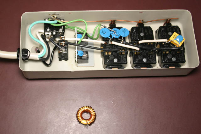
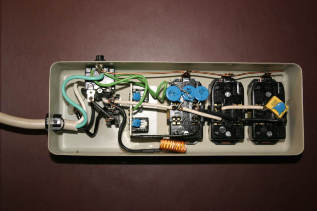
Construction was easy enough. I had a surge protector on the problematic A/V with a metal case. It is a relatively cheap surge protector with only simple MOVs, but it is good enough since I already have a whole house surge installed at the breaker panel. All I did was open up the hot (black) conductor between the switch/fuse and the first outlet. Then soldered in the inductor. The inductor leads were covered with shrink fit tubing. I should have wrapped the inductor with phenolic paper to make sure it doesn't short out to the case but I'm fresh out. (mental note: find a source for phenolic paper)Power Strip Before
Power Strip w/ Inductor
I would really like to have performed some real signal strength measurements, but I've never purchased a O-scope or X-10 strength meter. Maybe someone that lives in the DFW area can loan me one?
A few simple tests with a lamp module proved that the problem is solved. This goes to show that you don't need complicated test equipment to solve basic X-10 problems if you know a little theory. Ah, now to find another Saturday project.....
Last wiki comments